Blog > Image Acquisition > Inspection of Tapered Roller Bearings for a Global Bearings Manufacturer
Inspection of Tapered Roller Bearings for a Global Bearings Manufacturer
By – Raghava Kashyapa
Published on – 04-09-2022
Introduction
The customer, the Indian division of a global bearings manufacturer, approached Qualitas for a solution to automatic visual inspection of tapered roller bearings. The bearings were being produced in large numbers and needed to be in-line visually inspected for manufacturing surface defects on the cylindrical and larger flat surface. The surfaces were prepared by a combination of turning, grinding and honing. Occasional errors in these processes were leading to surface aberrations like scratches, machining markings, dents and other irregularities which could result in extra noise, additional friction and even corrosion during operational usage (FIG:1).
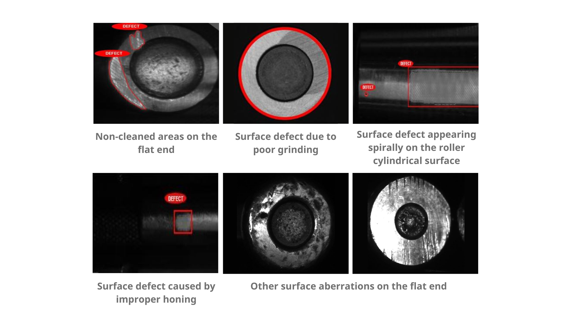
Fig – 1
The existing inspection process was batch oriented. Batches of various bearing SKUs would accumulate in large numbers during production runs and be visually inspected by large teams of human inspectors both randomly and individually in multiple shifts. Bearing surface defects, when present, would accumulate in large numbers due to the high production throughput (200 per minute across 6 parallel production lines) and late-stage inspection. Such defects were not random; they were usually created by some upstream tooling problem and would consequently present themselves in every produced part till the cause was rectified. This resulted in a variety of negative consequences: lowered factory productivity, increased scrap, rework, costs, and huge customer-induced reparations.
Solution
Qualitas was called in to conceive, design and implement an end-to-end inline visual inspection system that would minimize these issues. Qualitas provided both the image acquisition and the image processing pieces of this solution.
Image Acquisition
Three industrial cameras were installed for image capture: two for the cylindrical roller surface and one for the larger of the two end surfaces. The cameras and lighting were stationary; the design for managing varying part geometries across various SKUs was built into the material movement and handling systems. The cameras and lighting were designed and positioned to capture the roller surfaces maximally, though not completely (FIG: 2). As many surface defects manifested spirally, it was reasoned that these would be captured even without 100% camera surface coverage. But others like dents and scratches, which could appear randomly had a chance of going undetected due to finite camera coverage. This was considered an acceptable design compromise.
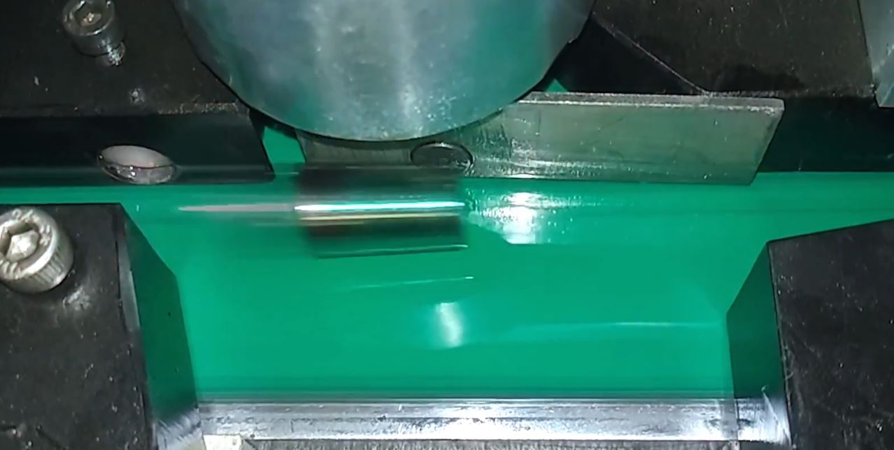
Fig – 2
The rollers moving down the production line varied considerably in diameter (12mm to 40mm) and length (10mm to 60mm), presenting some challenges for attaining sharply focused images for stationary, fixed-focal-length cameras.
The end-face capturing camera was triggered on the trailing edge to achieve a single working distance regardless of roller length. Mechanical guides were designed and installed to ensure that different sized rollers were snug and firmly in place during image capture as they passed through the inspection station (FIG:3, FIG:4). The variation in working distance for the cylindrical surface capturing cameras (12mm to 40mm diameter) also needed to be addressed. This was achieved in two ways. First by reducing the camera apertures (and thereby increasing depth of focus) and setting it to focus on mid-range, (12+40)/2, so that the focus changes caused by the two extremes could be minimized. Second, by increasing the light intensity to compensate for the loss of aperture.
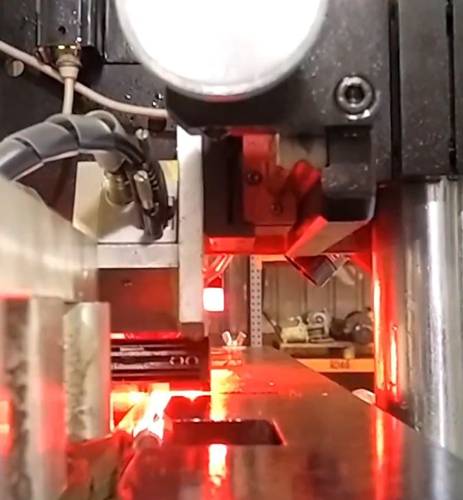
Fig – 3
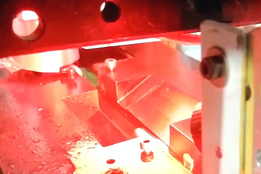
Fig – 4
Red lighting was used to reduce reflections and also to take advantage of the camera sensor’s superior quantum efficiency in that color wavelength (FIG:5).
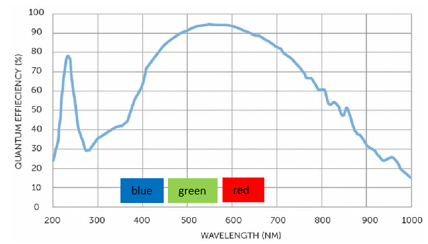
Fig – 5
The rejection mechanism consisted of a solenoid-driven flipper, adaptable to a range of roller sizes, that pushed the defective rollers out into a chute (FIG:6).
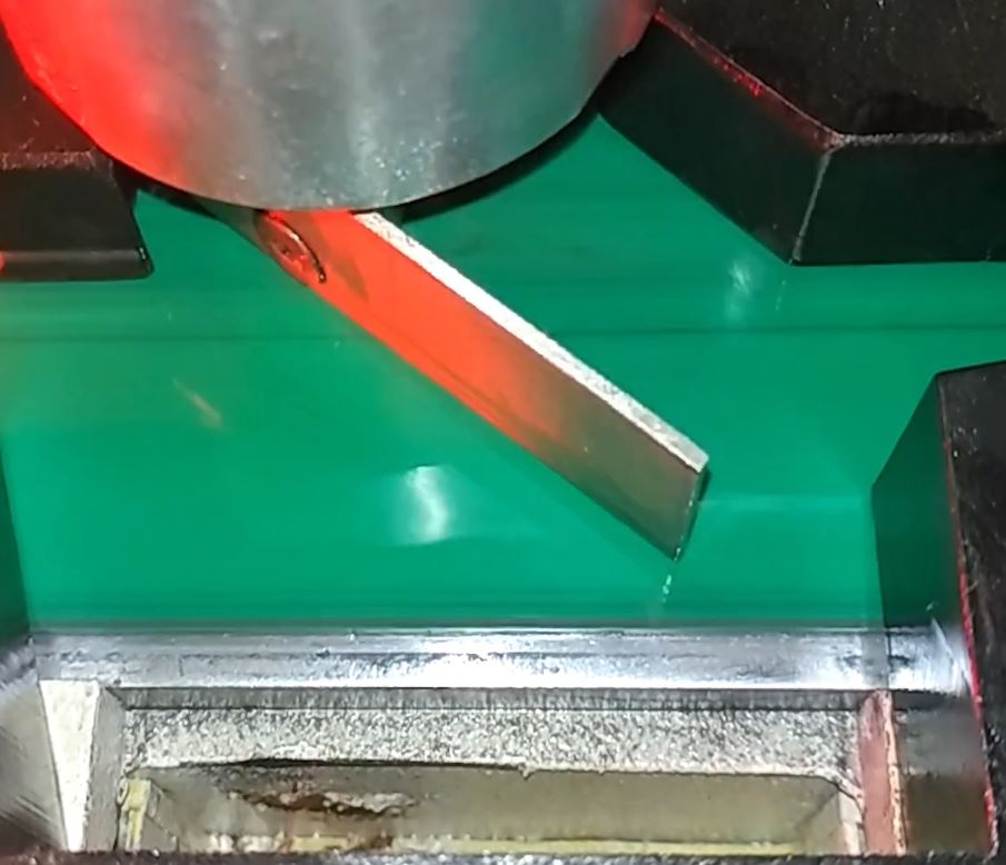
Fig – 6
Image Processing
It was decided to use a Deep Learning AI powered inspection technique since the defects were qualitative and across a wide range of roller SKUs. The key steps followed in this workflow consisted of image collection, image annotation, Deep Learning model selection/training, deriving an optimized Edge inference model, deployment on the production floor and, finally, maintenance.
Qualitas worked collaboratively with the customer to collect and annotate a sufficient number of good (G) and not-good (NG) images of the tapered rollers, showing both the cylindrical and larger flat surfaces. A few hundred images were thus collected and processed. This image data was used to train the chosen Deep Learning AI model iteratively till acceptable performance was achieved. A key consideration was to keep false positive and false negative predictions sufficiently low across the wide variety of SKUs for a range of subjective surface defects.
The software used was a combination of in-house developed solutions, collectively called QEP (Qualitas EagleEye Platform). QEP is a hybrid Cloud/Edge solution, wherein compute-intensive operations are performed on a public Cloud and performance/time critical functions on a local Edge computer. Qualitas integrated QEP into the factory environment as needed: PLC-intercommunication for the rejection mechanism, ERP-intercommunication, real-time notification to operators, data storage/retrieval, etc.
Conclusion
The image acquisition system turned out to be an elegant and economical design that minimized the number of cameras, the number of moving pieces and contributed to accuracy, robustness and extended system life. The image processing system was state-of-the-art, exceeding the customer’s accuracy expectations. The stated objectives of eliminating a late-stage inspection pileup, reducing reliance on human inspectors, and detecting defects earlier in the production pipeline were fully achieved.