What needed solving
Sub-millimetre tolerances, multi-surface geometry, and the mix of ceramic, metal, and electrode materials make manual inspection both slow and structurally unreliable.
At 20 ppm, each part is present for only 3 seconds — insufficient time for a human inspector to evaluate gap, eccentricity, thread, and surface defects simultaneously.
How Qualitas solved it
The suggested architecture uses three dedicated stations arranged in a linear or rotary indexing layout. Station 1 handles part loading and basic orientation validation. Station 2 performs all measurement and vision inspection using a Keyence system with top-view and front-view cameras. Station 3 executes the verdict — marking rejected parts with a tungsten carbide punch and physically sorting parts into good and NG bins via a rejection arm.
1. The Spark Plug End-of-Line Inspection Challenge
Spark plugs are safety-critical ignition components produced at high volumes for the global automotive market — serving engines in passenger vehicles, commercial trucks, motorcycles, and small equipment. Each plug must meet stringent dimensional, surface, and assembly specifications before leaving the production line. Sub-millimetre tolerances, multi-surface geometry, and the mix of ceramic, metal, and electrode materials make manual inspection both slow and structurally unreliable. A faulty spark plug reaching an engine can cause misfires, reduced fuel efficiency, elevated emissions, and catalytic converter damage. IATF 16949-regulated OEM supply chains demand near-zero PPM defect escape, placing extreme pressure on spark plug manufacturers to deploy 100% end-of-line inspection without sacrificing line throughput.
Key Inspection Dimensions and Stakes
| Inspection Dimension | Industry Benchmark | Business Impact if Failed |
|---|---|---|
| Electrode gap (front view) | +/- 0.01 mm for iridium grade | Out-of-spec gap causes misfire and elevated emissions Eccentric electrode degrades spark path |
| Centre electrode eccentricity (top view) | Sub-pixel X/Y offset | Eccentric electrode degrades spark path and ignition energy Non-compliant thread causes installation |
| Thread profile (front view) | ISO 13738 — 1 missing turn | Non-compliant thread causes installation failure at engine assembly Cracked ceramic causes high-voltage leak |
| Ceramic insulator crack | Zero tolerance — < 50 µm | Cracked ceramic causes high-voltage leak and no-start condition Surface damage promotes corrosion and |
| Shell dent / chip / burr | Dents >= 0.1 mm, burrs >= 0.2 mm | Surface damage promotes corrosion and mechanical failure in service Misloaded or curled parts jam |
| Part orientation / no-curl | Correct seating confirmed | Misloaded or curled parts jam downstream tooling |
2. Why Traditional Inspection Falls Short
These limitations are structural and cannot be resolved by additional headcount or training. The geometry, speed, and tolerance requirements of spark plug end-of-line inspection fundamentally exceed the capabilities of unaided human vision — making automated machine vision the only viable path to zero-PPM quality assurance.
★ Key Limitation: Human inspection of spark plugs at any meaningful production rate is structurally impractical. At 20 ppm, each part is present for only 3 seconds — insufficient time for a human inspector to evaluate gap, eccentricity, thread, and surface defects simultaneously. Manual feeler gauge gap measurement achieves only +/- 0.1 mm accuracy — ten times coarser than the +/- 0.01 mm required for iridium-grade plugs. Automated vision inspection eliminates this structural gap.
| Limitation | Root Cause | Quality Risk |
|---|---|---|
| Gap measurement accuracy | Manual feeler gauge operator skill Human eye cannot quantify sub-pixel | Error +/- 0.1 mm vs +/- 0.01 mm required |
| No X/Y eccentricity check | Human eye cannot quantify sub-pixel offset | Eccentric plugs escape undetected Cracked insulators escape to engine |
| Hairline crack miss rate | Human eye limited to cracks > 0.3 mm Thread gauges are sampling-based, not | Cracked insulators escape to engine assembly Galled or stripped threads reach |
| Thread inspection gap | Thread gauges are sampling-based, not 100% Human max 5–8 ppm sustained | Galled or stripped threads reach assembly line |
| Throughput limitation | Human max 5–8 ppm sustained inspection | Bottleneck vs 20 ppm production rate |
3. Suggested Three-Station Inspection Architecture
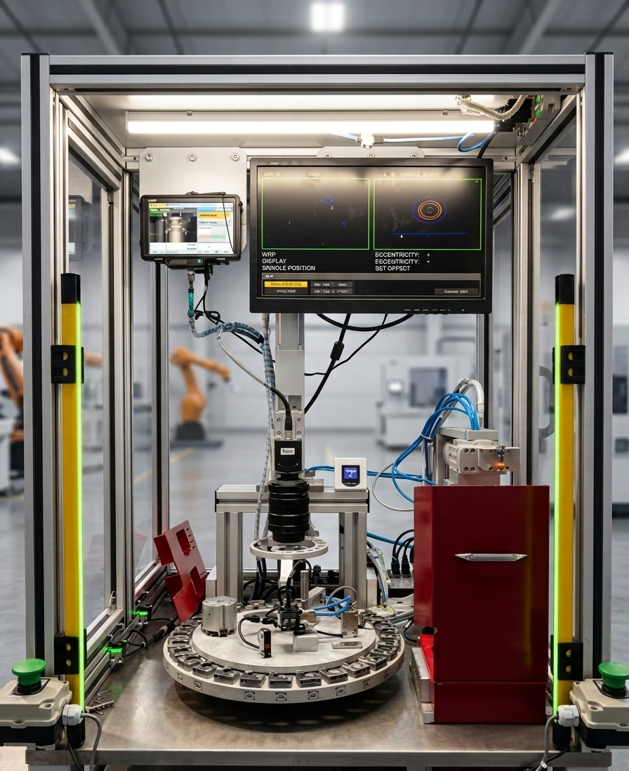
- Complete three-station spark plug end-of-line inspection system with rotary indexer, Keyence vision, and mark-or-reject.
The suggested architecture uses three dedicated stations arranged in a linear or rotary indexing layout. Station 1 handles part loading and basic orientation validation. Station 2 performs all measurement and vision inspection using a Keyence system with top-view and front-view cameras. Station 3 executes the verdict — marking rejected parts with a tungsten carbide punch and physically sorting parts into good and NG bins via a rejection arm. Good parts loop back to Station 1 where the operator collects them.
Station 1 — Part Loading, Unloading, and Orientation Check A robotic pick-and-place mechanism or bowl feeder loads spark plugs onto the inspection indexer. Before advancing to vision inspection, Station 1 confirms: part presence (plug loaded correctly), correct seating orientation (not tilted or curled), and absence of gross mechanical interference. Parts failing the orientation check are diverted immediately without consuming vision cycle time. After Station 3 clears the verdict, good parts are returned to Station 1 where the operator picks them for downstream packaging.
- Rotary indexing table with spark plug fixtures (AA / AE / AF / BA etc positions shown).
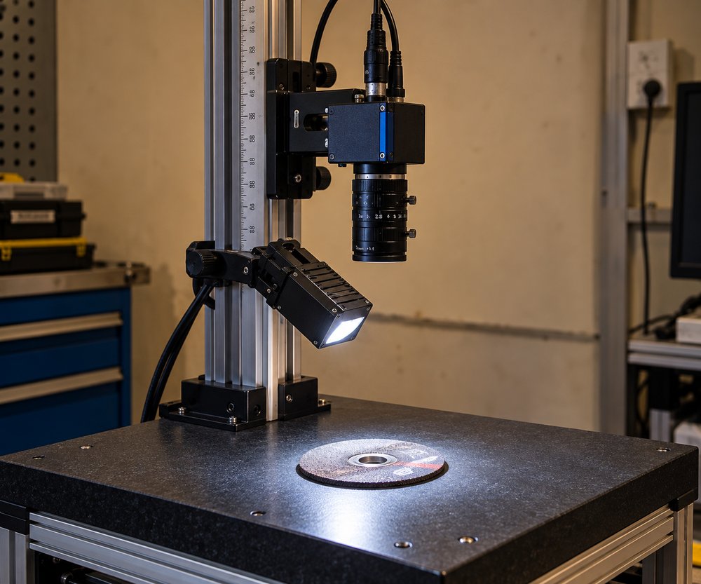
Station 2 — Keyence Top and Front View Vision Inspection Station 2 is the core measurement and inspection station, using a Keyence vision system with two cameras: a top-view camera capturing the electrode tip and ceramic nose from directly above, and a front-view camera imaging the electrode gap, thread profile, shell body, and side geometry. The top-view camera measures centre electrode X and Y eccentricity with sub-pixel accuracy. The front-view camera measures the electrode gap to +/- 0.01 mm resolution, verifies thread pitch and continuity, and detects surface defects on the insulator and shell. A deep learning classification layer handles hairline cracks and low-contrast anomalies that rule-based algorithms would miss. Every plug at Station 2 generates a structured result record — GOOD or NOT GOOD — which is passed to Station 3 for physical action.
- Keyence BVS4 home screen displaying real-time gap, overlap, spark position, and eccentricity measurements for an inspected plug. Top-down view of the rotary indexer showing camera arrangement above the spark plug fixture ring.
Station 3 — Mark, Sort, and Return Station 3 is the action station. When the verdict from Station 2 is received, the station executes one of two paths. For a GOOD result: a pneumatic cylinder carrying a tungsten carbide tip descends and punches a permanent dot onto the surface of the spark plug — providing an indelible physical pass mark that confirms the part has cleared all inspection checks. For a NOT GOOD result: a rejection arm picks the part and drops it into the appropriate NG bin based on the specific rejection criterion (gap, thread, crack, eccentricity, or other). This two-action approach — positive pass mark on conforming parts, physical removal of non-conforming parts — ensures zero-PPM escape even in the event of downstream handling mix-ups.
Detection Capabilities
| Defect / Parameter | Detection Method | Camera View | Sensitivity / Standard |
|---|---|---|---|
| Electrode gap out-of-spec | Telecentric imaging / profilometry Sub-pixel vision | Front view | +/- 0.01 mm — OEM spec |
| Centre electrode X/Y eccentricity | Sub-pixel vision measurement | Top view | Sub-pixel offset detection |
| Ground electrode misalignment | AI pose estimation | Front view | +/- 2 degrees angular |
| Ceramic insulator crack | DL anomaly detection | Front view | >= 50 µm crack width |
| Shell dent / chip | Rule-based edge + DL | Front view | >= 0.1 mm depth |
| Metal flash / burr | Rule-based blob detection | Front view | >= 0.2 mm protrusion 1 missing thread turn — ISO |
| Thread damage / galling | Thread vision gauge | Front view | 1 missing thread turn — ISO 13738 |
| Missing gasket / seal | Presence detection + colour | Front view | Binary pass/fail |
| Part orientation / no-curl | Shape + edge detection | Top view | Station 1 pre-check |
4. Expected Outcomes and Indicative ROI
The figures below are indicative estimates derived from published machine vision deployment data in automotive component inspection. Actual outcomes will depend on baseline defect rates, current scrap and rework costs, and facility-specific production parameters. A pilot study using pre-classified good and defective parts is recommended before full deployment to validate detection performance and establish facility-specific ROI.
★ Station 3 Design Note: The tungsten carbide punch mark on NG parts is a critical safety feature of this architecture. Even if a rejected part is accidentally picked up by an operator or mixed into good stock downstream, the permanent physical dot provides an unambiguous visual and tactile signal that the part is non-conforming — eliminating the risk of zero-PPM escape through human handling error.
| Outcome Area | Indicative Improvement | Enabling Mechanism |
|---|---|---|
| Defect detection rate | > 99.5% on trained defect classes | Top + front cameras with DL inference |
| Electrode gap accuracy | +/- 0.01 mm (10x manual improvement) | Telecentric front-view measurement |
| Eccentricity detection | Sub-pixel X/Y — new capability | Top-view Keyence camera |
| Throughput vs manual | 3-4x increase vs manual inspection | 20 ppm automated vs 5-8 ppm manual Physical marking prevents downstream |
| Zero PPM NG escape | WC punch mark + bin sort | Physical marking prevents downstream mix |
| Traceability | Per-plug digital result record | SQL log with station ID and timestamp |
| IATF 16949 readiness | Automated audit-ready records | Digital traceability replaces paper logs System replaces manual inspection |
| Labour redeployment | 1-2 FTEs per shift redeployed | System replaces manual inspection posts |
| Recall exposure reduction | Targeted by lot / shift / cavity | Per-plug DataMatrix traceability link |
| Payback period | 12–24 months (indicative) | Scrap cost + rework + inspection labour |
5. Implementation Considerations
Phased Deployment Approach The recommended starting point is a feasibility study (4–6 weeks) to confirm camera configurations, lighting strategies, and line integration requirements for the specific plug family and line speed in use. A proof-of-concept using 500–1,000 pre-classified good and defective plugs validates detection performance — particularly gap measurement accuracy and eccentricity sensitivity — before capital commitment. Production deployment proceeds station by station: typically Station 2 (vision inspection) first, then Station 3 (mark and reject) integration, then Station 1 (automated loading) if not already in place. Facilities operating multiple plug families (standard copper, platinum, iridium, multi-electrode) should plan a recipe-per-model library from the outset. Recipe changeover is automated via production order barcode scan, enabling the system to switch between plug families in under 60 seconds without mechanical adjustment — a critical capability in high-mix production environments.