Blog > Image Acquisition > Illumination In Image Acquisition – Showing Images In The Best Lighting
By – Raghava Kashyapa
Published on – 02-09-2022
Machine vision (MV) has become one of the most prolific applications of machine learning and is used extensively in industrial and non-industrial settings. As discussed in our lead story, the success of an MV system depends on its capability to acquire an image, process and inference it, and produce an accurate pass-fail decision in an industrial inspection process. It’s to be noted that the camera actually ‘sees’ the object, by virtue of the light reflected by it. Thus, controlling the illumination or lighting on the object during the visual inspection holds the key to making the features ‘visible’ to the camera.
Light as we see it
When we speak of light in general, it is in the context of the the “visible portion” of electromagnetic spectrum perceived by the human eye. It carries energy in the form of waves or particles through a medium, and is typically characterized by it’s wavelength. The visible spectrum comprises of wavelengths in the 400–700nm band and lies between the infrared (longer wavelengths) and the ultraviolet (shorter wavelengths) of the electromagnetic spectrum (FIG 1).

Fig – 1 (Visible Spectrum)
Effect of lighting on image acquisition
In industrial inspection, the primary aim of lighting is to maximize contrast for the features of interest, and minimize contrast outside of it. To achieve this, it is crucial to understand how sample contrast can be manipulated and enhanced using the three fundamental factors that affect lighting –Spatial Configuration, structure (or pattern) and wavelength (or color). These aspects have a direct bearing on the image. Accomplishing contrast changes via spatial configuration requires moving the inspected object, light, and camera position until a suitable configuration is found. Contrast changes via structure involves changing the light pattern via shape of the light (spot, dome, sheet, or line) projected on the sample along with the lighting technique. Changing the spectrum of light via color or wavelength produces contrast changes that are related to differential color absorbance vs. reflectance of the inspected object and its background. Filters can also be used to increase the contrast for viewing features that may not be highlighted in white light.
Design considerations for optimal lighting solution
Two aspects that need to be factored in when determining optimal lighting are – the light interaction with the object to be inspected and the immediate inspection environment.
Light Interaction with inspected object: The surface shape, geometry, texture, reflectivity, color, topography and even the composition of the object under inspection can affect how the object interacts with the lighting. A single or a combination of these factors determine how much light is reflected back to the camera and is eventually available for acquisition, processing and analysis (FIG 2). Highly reflective or transparent surfaces require specialized illumination techniques to facilitate the capture of useful image data. Similarly, parts with a topographic surface, flat but finely textured surface, or a curved specular surface, all reflect light differently.

Fig – 2 (Light interaction with objects – image: photonics.com)
Color of objects also governs the type of illumination because objects appear differently when viewed under varied light wavelengths and conditions. The composition of the objects whether it is metallic, nonmetallic, polymer or mixed also influences the lighting choice.
Inspection environment: Color of objects also governs the type of illumination because objects appear differently when viewed under varied light wavelengths and conditions. The composition of the objects whether it is metallic, nonmetallic, polymer or mixed also influences the lighting choice.
Based on the aforementioned factors let us now have a look at different illumination sources and techniques that can help resolve the various challenges in a machine vision system deployed on a production line for visual inspection.
Illumination sources
There are a wide variety of light generating sources that can be employed. A few of them are halogen lamps, fluorescent light, Xenon, laser units, metal halides and LEDs. Metal halides are used in areas that require a very bright source (5600 K). Since it has many discrete wavelength peaks, it is often used in microscopy. The most common source of lighting that is emerging in MV systems is LED illumination. The main reasons are – the small size of LEDs that enables creation of highly-flexible lighting arrangements, availability in a range of colors, achieving desired intensity by installing in arrays, and superior switching capabilities with the response speed being in the order of nanoseconds. A comparative insight into the characteristics of different types of lighting sources is depicted in FIG 3.
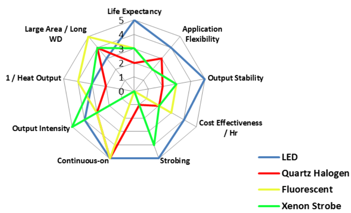
Fig – 3 (Primary Light Sources and comparison of their characteristics – image: visiononline.org )
Illumination techniques
Lighting affects the contrast in images which is one of the most fundamental characteristics for feature generation and pattern recognition in machine vision, and the use case dictates the technique and intensity of the lighting to be used. Some of the most commonly used lighting techniques (FIG 4) are discussed in the subsequent paragraphs.
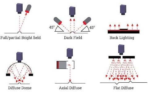
Fig – 4 (Lighting Techniques – image: iqsdirectory.com)
Bright and Dark field lighting: In the bright field technique, the object is illuminated from the front and the light reflected from the object is captured by the camera. In this form of illumination the features on the surface are highlighted and raised edges and details appear dark, and is therefore used in applications where the background and flat parts of the object need to be inspected.
In dark field lighting, the object is illuminated from a shallow angle (10 to 45 degrees) with respect to the target. The uneven reflection from vertical features on the surface highlights the raised edges and details while the background remains dark. This technique can be used for inspection of defects such as scratches, imprints, engraving, etching or protrusions, and even dust and fingerprints (FIG 5)
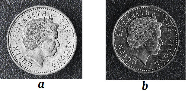
Fig – 5 (Bright field lighting(a) and Dark field lighting(b) – image:clearview-imaging.com)
Front and Backlighting: In front lighting, the light source is on the same side of the scene as the camera creating an excellent contrast but may also create shadows. This lighting technique is useful when creating shadows is desired for enhancing contrast in low-contrast images.
In backlighting, the light is behind the object, opposite to the camera, thus highlighting the silhouette of the object. Backlighting is used to detect the presence/absence of shapes like holes and gaps in opaque objects and verify their outlines. This technique is also used for seeing through transparent objects like films, glass, and plastic to detect defects like internal aberrations, air bubbles and scratches, and fill levels in bottles and jars. (FIG 6)
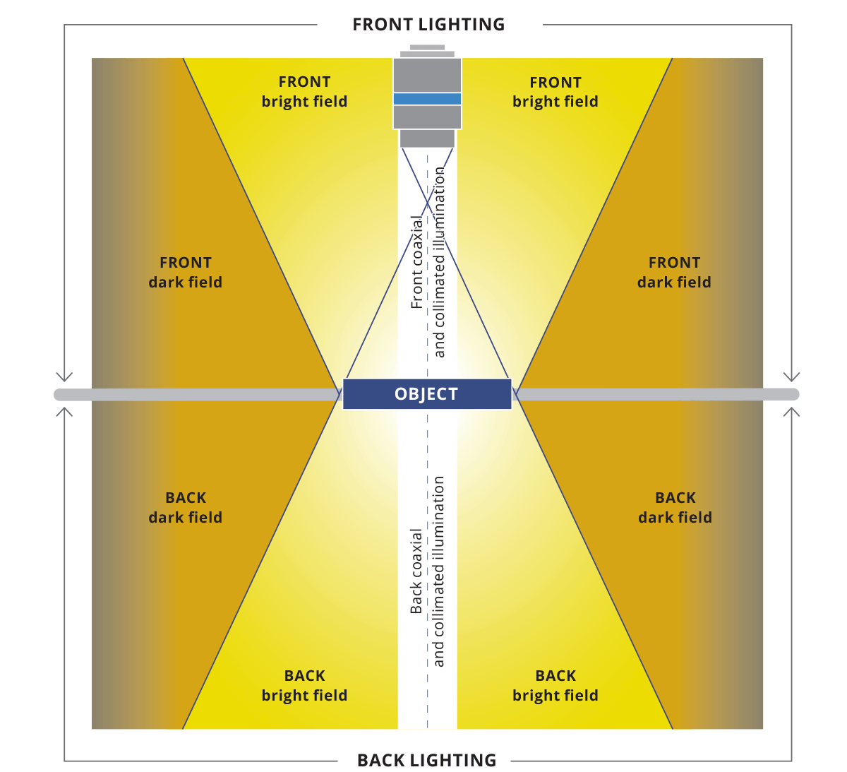
Fig – 6 (Illumination and directionality – image:opto-e.com)
Directed and Diffused lighting: Directed light illuminates every point on the scene with a single light ray or a group of rays that are spread in a very narrow range of angles. It tends to cast strong shadows and make texture stand out in the image.
Diffuse illumination illuminates every point on the scene with a bundle of rays coming from a wide range of angles. It casts faint or no shadows and eliminates the shading that makes texture evident in the image. This type of arrangement is frequently used to minimize glare and hide unwanted features, which comes in handy when detecting flaws on shiny, flat surfaces, and transparent objects.
Co-axial lighting: The coaxial light transmits light from the side onto a halfway mirror which reflects the light onto the target. Specular reflected light is allowed to pass back up to the camera whereas diffuse reflected light from the target is rejected, thus causing a contrast at the edge points of a target (FIG 7). This technique is ideally suited for applications such as PCB inspection, polished silicon wafers, reflective labels, or print inspection.
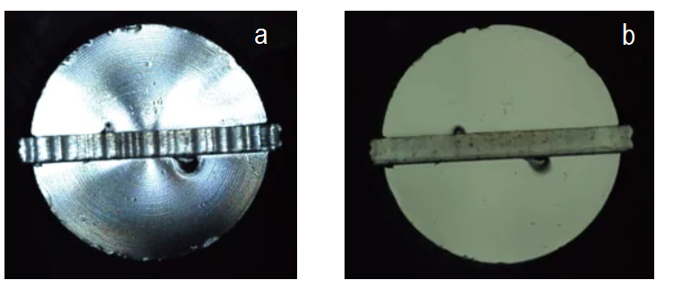
Fig – 7 (Inspection of screw heads with (a) standard lighting that is being reflected at all alignments (b) coaxial lighting where change from curved to flat is clearly identified – image: keyence.com)
Structured light: Structured lighting technique typically makes use of highly-collimated light sources such as lasers or fiber optic line lights, to obtain dimensional information. This is an inexpensive technique to measure depth and height of continuous surfaces and is often used when either the light source or the surface are moving. Aberrations on flat and highly reflective surfaces can easily be detected by using this technique.
Shapes of Lights
Once the lighting technique, whether specular reflection, diffused reflection, or backlighting, has been selected according to the shape of the target and the inspection purpose, the shape and size of light (FIG 8) to capture an optimum image for processing can be decided. Some basic options are:
- For specular reflection: coaxial illumination, ring illumination, or bar lights
- For diffuse reflection: low angle lights, ring illumination, or bar lights
- For backlighting: area illumination or bar lights.
Ring illumination and bar lights are commonly used because they can be used for various purposes by adjusting the installation distance.
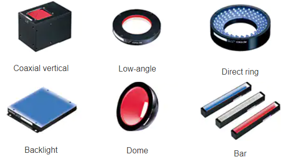
Fig – 8 (Shapes of lights – image: keyence.com)
Color and wavelength of lighting
The last step is to determine the color of illumination as per the target and its background. Usually color cameras along with white light are the first choice when objects are to be distinguished on the basis of color.
Sometimes however we may need to ‘highlight’ certain wavelengths more than others to increase the contrast of the features of interest. Using color bandpass filters with monochrome cameras is an efficient and cost-effective way to accomplish this. For example, green filters are used in the pharmaceutical industry to inspect red and green colored capsules, which enhances the contrast by more than 85% (FIG 9). Similarly, blue filters can be used to detect small defects since the scattering in shorter wavelengths (blue color) is higher than that of longer wavelengths.
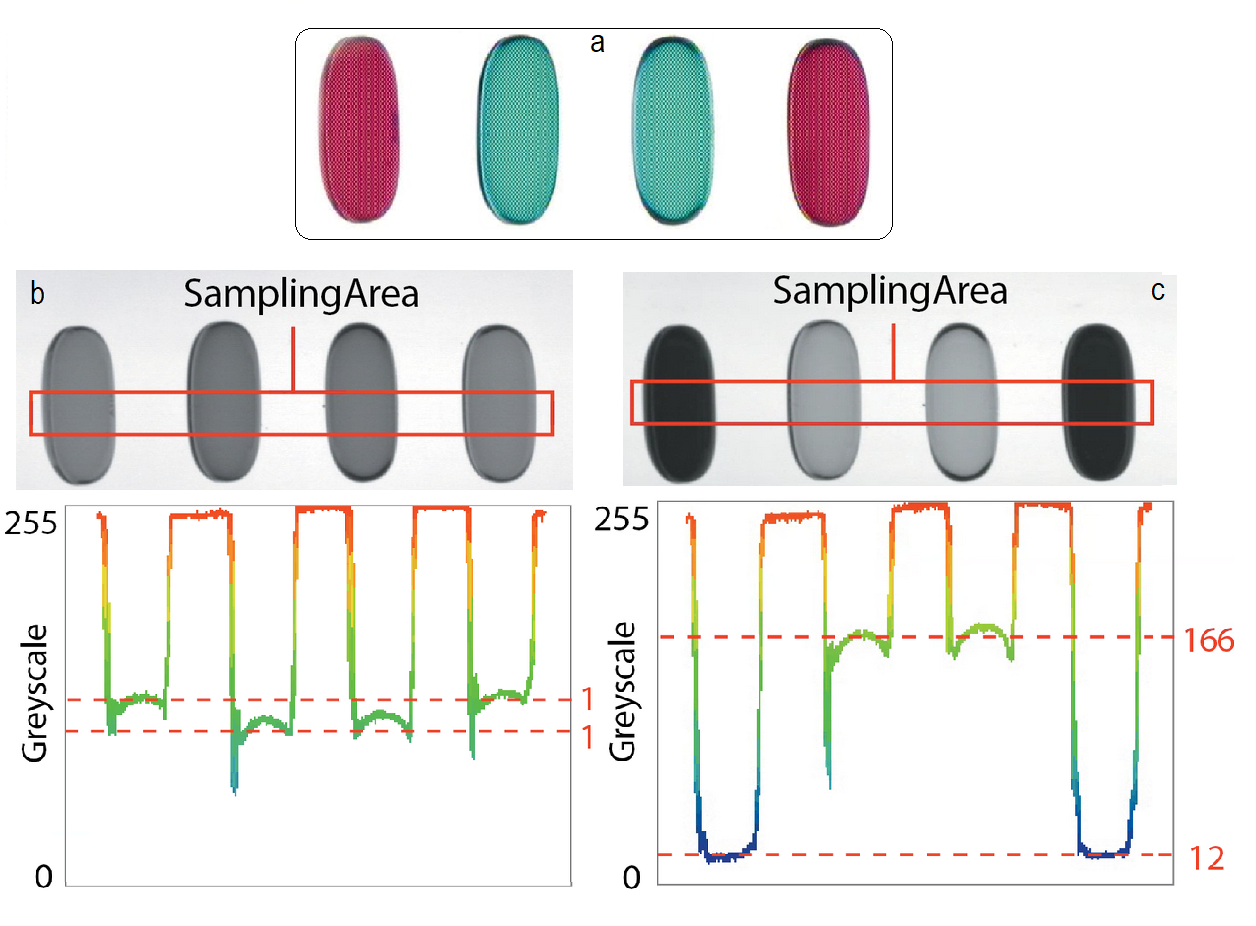
Fig – 9 ((a) Four liquid capsules under inspection shown in color, (b) capsules viewed with a monochrome camera yield a contrast of 8.7%, and (c) with a monochrome camera and green filter yield a contrast of 86.5%. – image: edmundoptics.com)
The use of ‘invisible’ lighting typically Infrared or Ultraviolet color lighting can be used to enhance contrast with difficult to see materials. Infrared light interacts with sample material properties, often negating color differences and can penetrate materials more easily because of the longer wavelength while ultraviolet light is used usually to make parts fluoresce. The images below (FIG 10) illustrate how different types of lighting can affect the contrast in imaging.
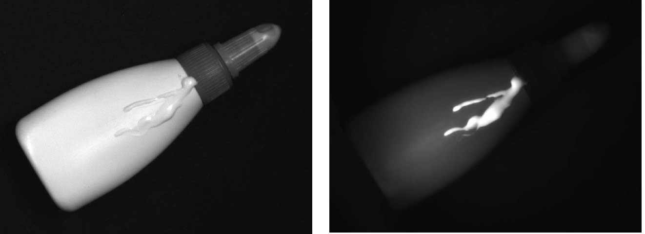
Fig – 10 (Hard to see white glue on plastic bottle fluoresces and appears bright under UV radiation -image:vision-doctor.com)
Lighting the way
There is no doubt that suitable illumination is one of the most critical aspects to achieve a high image quality for machine vision systems. Ideally, lighting should be bundled with the image acquisition system, since the sub-systems including the triggering mechanism are harmonized with each other. However, with the increasing availability of modular components and manufacturers opting for them, a clear understanding of the business case becomes critical, and certainly calls for considerable experience.
Qualitas Technologies, with its vast expertise in having developed more than 200 machine vision systems provides requisite guidance for the selection of illuminations and avoiding a costly and time-consuming process of trial and error.