Why Inspect Before Foam Filling?
Refrigerator insulation is formed by injecting polyurethane foam between the outer cabinet and the inner liner. A crack, hole, or poorly formed liner feature can create a potential path for foam to escape or compromise the intended insulation build. After the cavity is filled, the relevant surface is no longer available for direct inspection.
This is a feasibility-trial application note, not a claim of a completed production deployment. Its purpose is to show how a repeatable image-acquisition and AI-assisted inspection process can be evaluated on the actual liner variants, sample conditions, and line constraints.
| Risk | Why it matters |
|---|---|
| Late discovery | A relevant surface is hidden after the foam-filling operation |
| Manual inconsistency | Difficult-to-view regions can be interpreted differently between operators or shifts |
| No decision evidence | An image-backed outcome supports review, debugging, and agreed escalation |
Proposed Inspection Architecture
A part-present signal selects the correct recipe; a camera and controlled illumination capture the target regions; and inspection software evaluates those regions against a validated model or ruleset. Each cycle can create a result record with the relevant image, timestamp, variant or recipe, and reason code.
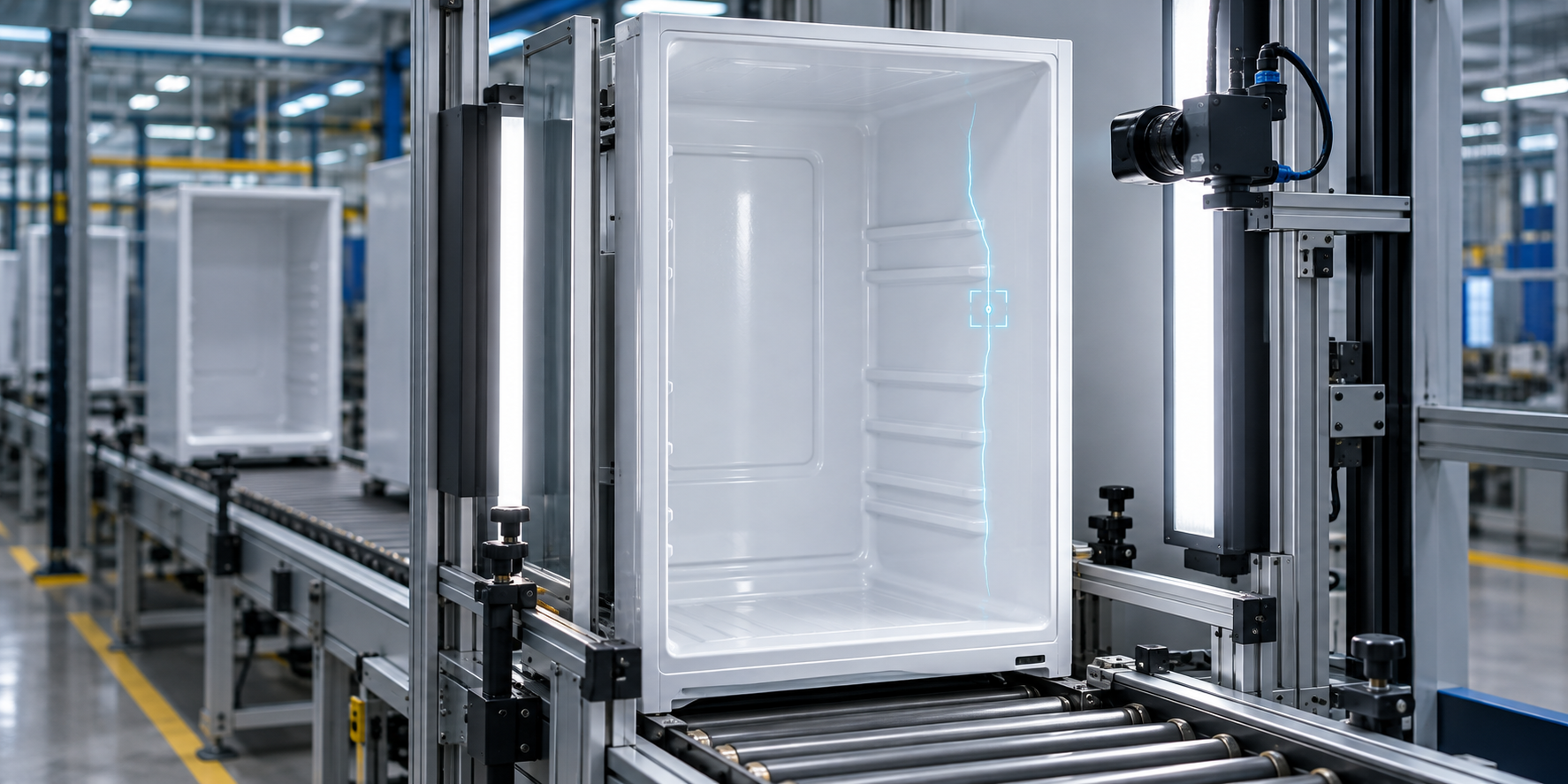
- Use controlled lighting selected from sample-image validation, rather than assuming one lighting method fits all liner geometry and surface finishes.
- Define region-specific recipes so cabinet geometry outside the inspection scope does not influence the result.
- Connect a validated outcome to an operator screen, line PLC, review queue, or plant data system according to the agreed workflow.
Validation Criteria That Matter
A useful pilot first builds a labelled reference set: representative good parts, known defect or boundary examples where available, actual part variants, and the expected operating environment. The system result is compared to the agreed reference inspection before it is considered for production use.
| Measure | How it is established |
|---|---|
| Coverage | Confirm that selected regions are reliably visible on the customer’s liner variants |
| False accept / false reject | Compare the inspection result with the agreed labelled reference set |
| Cycle time | Measure trigger-to-result timing in the intended handling and line context |
| Traceability | Agree which images, results, recipe data, and reason codes must be retained |
The downloadable app note explains the full staged path from feasibility through line integration and production handover, including the inputs needed for lighting, fixturing, change control, retention policy, and exception response.
From Trial to Production
The recommended sequence is straightforward: establish image coverage and distinguishability; validate agreed quality metrics on the labelled sample set; integrate the approved station into the physical and control environment; then document its operating limits and support process. Performance targets are acceptance measures established on the actual part family and line, not generic numbers quoted in advance.