Case studies > Steel Industries > Critical Inspection of Gearbox Assemblies for an Automobile
By – Raghava Kashyapa
Published on – 14-09-2022
The customer is one of the largest independent manufacturers of powertrain and precision engineered products. They have been consistently delivering competency across the entire value chain of design and manufacture of engines, transmissions, and high precision components. While assembling gearboxes, it was critical to ensure that circlip and sleeve components were correctly aligned and positioned, as errors could cause gearbox malfunction, damage, and even failure.
Problem Definition
Avoiding misalignment of circlips and sleeves during gearbox assembly through a visual inspection process.
The following visual inspections were required:
- that two kinds of circlips (round and starred) were present in their designated locations.
- that the circlips were fully seated and engaged to perform their function on the gear shafts.
- that a circular sleeve component was appropriately oriented and seated.
Solution and Implementation
The partially assembled gearboxes were being moved down a production line and would be directed to the visual inspection station for imaging and inspection. (FIG:1 and FIG: 2).
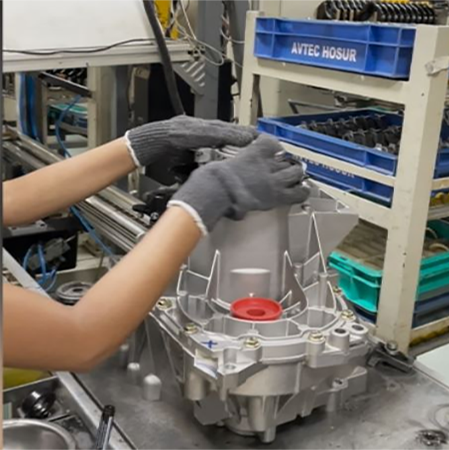
Fig – 1 (Operator at the production line preparing a gearbox for inspection)

Fig – 2 (Operator places gearbox at visual inspection station)
The image acquisition hardware comprised a single camera and light source. The camera and lighting orientations were designed to produce a single, unambiguous view of the whole region of interest from which all conclusions could be drawn. The parameters and settings of the camera were designed to produce a clearly focused image of two parts of the gearbox that were at slightly different working distances.
This image was transferred to a nearby Edge processor (an industrial computer) in near-real-time which executed the QEP (Qualitas EagleEye Platform) software’s Deep Learning-based inferences. Any error found in inference would activate a nearby alarm to inform the operator to investigate further. In addition, the specific problems identified were clearly indicated on the screen display of the Edge processor. The operator would view these errors this (Fig 3) and proceed to manually correct them prior to restarting the production run.
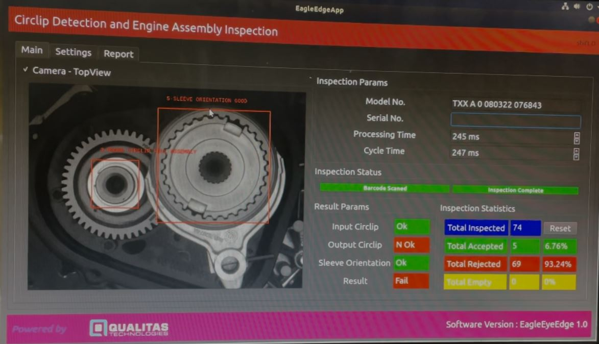
Fig – 3 (The QEP inference screen at the inspection station)
The required number of ‘good’ and ‘not good’ image samples were collected by capturing and monitoring sufficient imagery through the image acquisition setup that had been first installed on a regularly running production line.
These images were used to develop and train the chosen Deep Learning neural network models after being inspected and annotated using QEP software tools. Object detection and image segmentation were the QEP Deep Learning modules used. The presence or absence of the two types of circlips was determined using object detection. (FIG:4 and FIG:7).
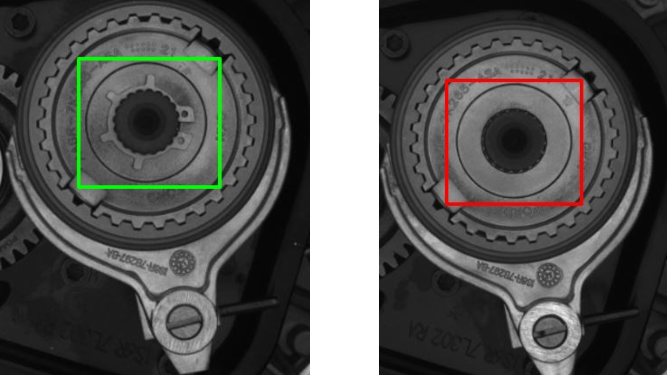
Fig – 4 (Gearboxes with (good) and without (not good) the round circlip)
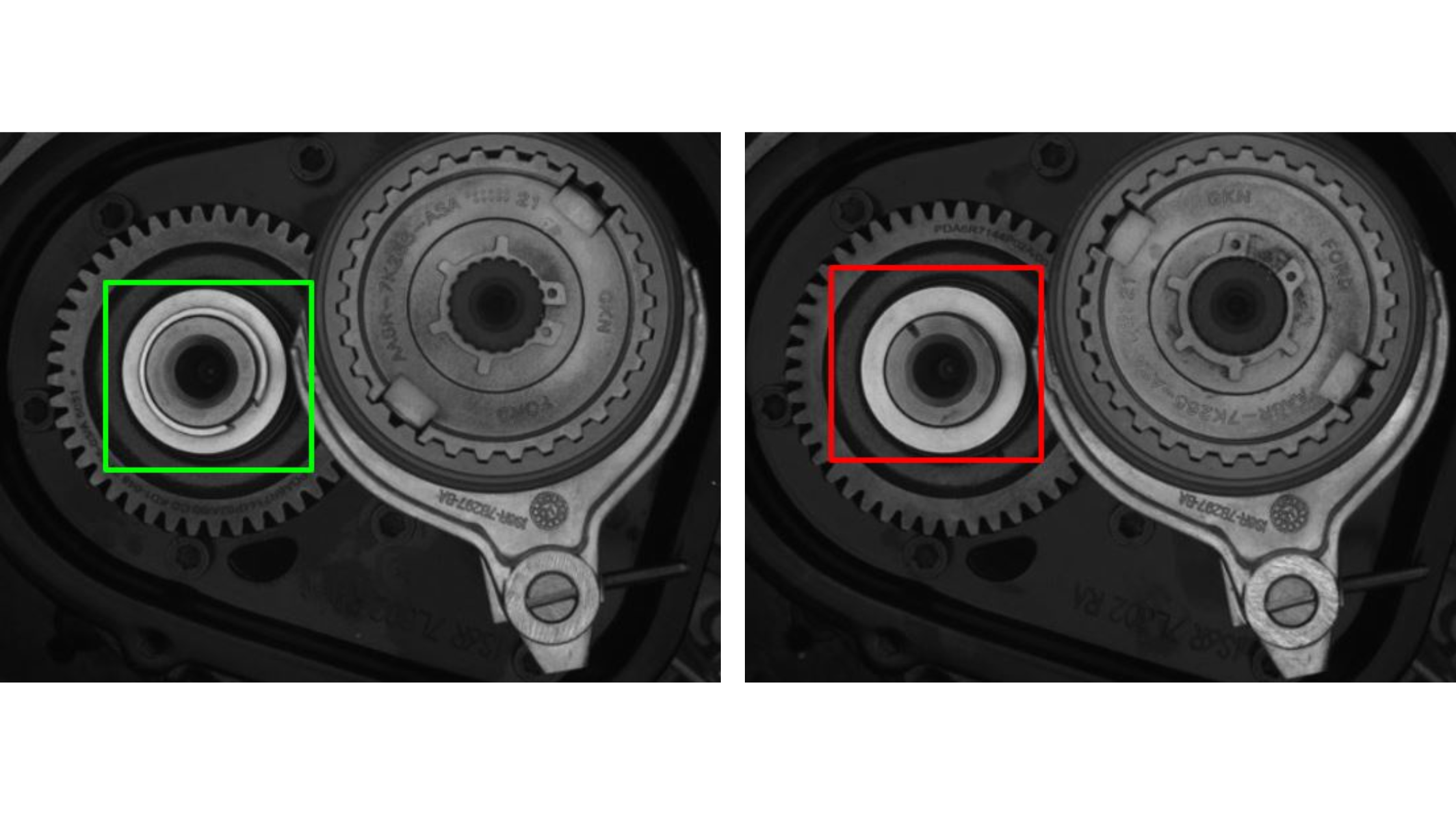
Fig – 7 (Gearboxes with (good) and without (not good) the star circlip)
Object identification and image segmentation were used to determine whether the circular sleeve was positioned properly (FIG:10). Similar Deep Learning procedures, together with precise pixel-level counting and measurement, were employed to ensure that the circlips were properly seated and aligned (FIG: 5, FIG:6, FIG:8, and FIG:9).
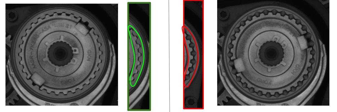
Fig – 10 (A properly seated and oriented sleeve (good). An improperly seated and oriented sleeve (not good))

Fig – 5 (A properly seated round circlip (good). Circumferential end spacing is correct)
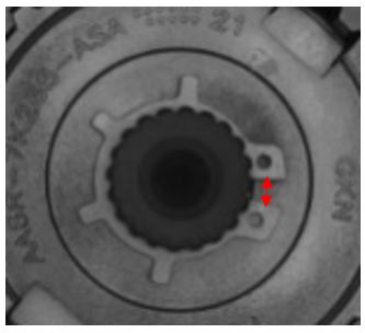
Fig – 8 (A properly seated star circlip (good). Circumferential end spacing is correct)

Fig – 6 (An improperly seated round circlip (not good). Circumferential end spacing is excessive)

Fig – 9 (An improperly seated star circlip (not good). Circumferential end spacing is excessive)
Conclusion
Approximately four calendar months were spent on the entirety of the project, beginning with image data collection and concluding with the signoff of a fully functional system. The average accuracy of the many different inspections that were provided was greater than 99%, which completely fulfilled the requirements of the customer.